
A design series on embedded electronics and audio design.
Applying power to pedals should be a simple thing, but as designers we have to understand that if something can go wrong, it absolutely will. Or said another way, if a user can do something stupid, they will…
So I thought I’d dig in on what reverse polarity protection options are out there and / or make sense to protect pedal circuits from mis-applied power.
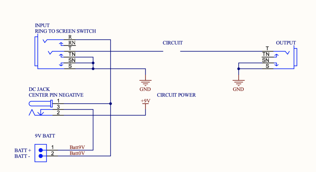
Let’s start with the typical power switching circuit for a pedal that has a battery and power jack, to understand how it works.
So quick run-through of what happens and when.
Battery powered (no DC power) – battery is actually isolated until the input jack completes the connection to circuit ground. This is really key to understand – the screen and ring connections of a stereo jack are used like a switch on the barrel of the (mono) input jack to complete the ground circuit connection. This is done to save battery power – the circuit is powered on only when you put the input jack in.
Two things are of note immediately – changing a battery and connecting it backwards will do no damage if there is no input jack in place. But! If the jack is present, we need a reverse polarity protection mechanism… Second, when designing PCBs, we need to remember that the input jack is our ground input…
Note the DC jack has a switching function here also – this time on the positive side. With no DC power jack inserted, the battery 9V connects to the circuit via the shorted ring connector on the DC jack.
DC powered – when a DC jack is inserted, it isolates the battery, and feeds the input voltage to the circuit instead. If a battery is in the case, it is isolated. Again, anther useful observation is that if you only power your pedals with external power supplies, and never use batteries, then you don’t need to worry about the battery terminals rattling against the case metal. You don’t need to wrap it in tape or anything else – it can’t do any damage. Obvious caveat – the ground connection on the battery clip should be kept away from components on the circuit board!
Another observation about the DC power jack on (almost all) guitar pedals – they have an odd polarity! The center pin is negative (0V or GND) – and that is the opposite of almost all other power connectors on consumer appliances. It would seem way more sensible to have a DC jack with the outer connection and possibly shell be ground, since we would likely want the case to be grounded for screening purposes… So, if you try to use a household jack, it will be the wrong way round. Thankfully most consumer power bricks are 2.5mm and center-positive, whereas guitar pedals are 2.1mm and center-negative.
However, there are guitar pedals made the ‘other or ‘right’ way round – and any good pedal power supply unit comes with cables for these opposite / legacy connections – so be careful!
Anyway, applying power to a DC jack, or via the battery clip, the wrong way round will cause damage if the circuit is not protected.
So with my observations and opinions out of the way, let’s look at circuits…
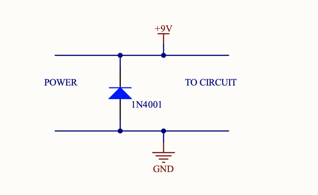
1. Silicon Diode across power rails
I’ve done this. It’s bad, but I’ve done it… There I feel better already…
Probably the most popular method of polarity protection (sort of) is to apply a beefy silicon diode (1N4001 or similar) across the rails to protect the circuit. So yes, with a reverse voltage applied, this will protect the circuit, but makes your 9V battery into a nice heater. Try it 😉
A fresh alkaline can source 1A or more, but the voltage will sag rapidly – say to 4V or less, but still an amp is an amp… So we will get lots of heat in the battery.
(Don’t ever think you can do this with LiPos – they will literally blow up…)
1a. Silicon Diode across power rails, with added fuse series resistor
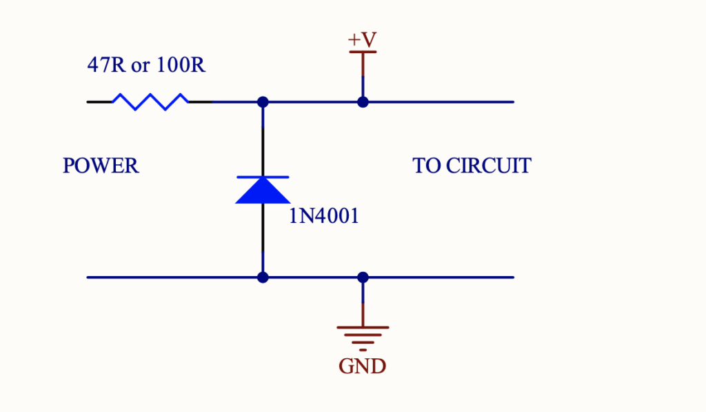
So to limit the reverse current, we can add a series resistor. The upside is we no longer get huge fault currents, but the downside is the voltage drop across this resistor – which is in circuit at all times – and the power dissipated in the resistor.
ProCo Rat has such a circuit. A 1/4W 47R or 100R resistor. If we consider the 1A current capability of a 9V battery, or that most power supplies will provide 500mA, then these resistors are really just fuses, and eat useful power at all times the circuit operates… Caveats again – yes they might survive short duration ‘doh’ moments of battery wrong connections, but it’s a bad engineering choice.
And yes you can use much larger power resistors, but really – think of all that sad lost power we are turning into heat instead of delicious tone 😉
Quick side thought on fuses. Resettable fuses do exist – I’ve used them in motor-related products. Their downsides are the very high (proportionally) trip currents, and relative slow response times. They do however, interrupt a fault current, and reset after it has been removed. It’s worth surveying new devices to see if the specs could work for this protection scenario…
2. Silicon or Schottky on input rail
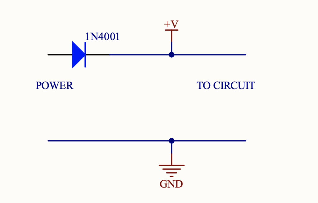
Another obvious and widely used technique is to place the protection diode in circuit. A silicon diode (Vf around 0.6V) or better Schottky (Vf around 0.45V) can be used.
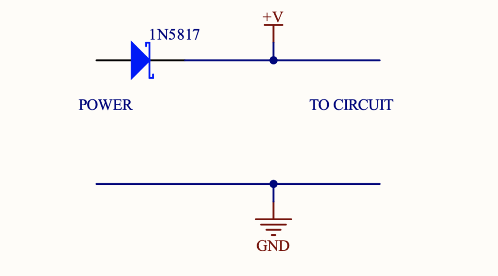
This approach does provide protection, but the obvious downside is that always present voltage drop.
That said, even before I talk about more complex circuit topologies, I think a Schottky diode used like this is likely the best bang for the buck protection for most pedals – it’s simple, low cost and loses only a small amount of input voltage to the protection.
3. MOSFETs
MOSFETs are the last option I will examine. These circuits are more complex (at least to design correctly), more expensive, use more board (real estate) area, can be very difficult to find for through-hole options, requires care in selection, but technically the best solution. I say technically best as we get reverse polarity protection, with only a tiny voltage (in the realms of tens mV??) loss to the FET device during operation. Ideally we’d like the protection to be ‘invisible’, but heh, engineering is all about compromise!
We can use PFETs or NFETs. Let’s start by looking at PFETs and how to select one.
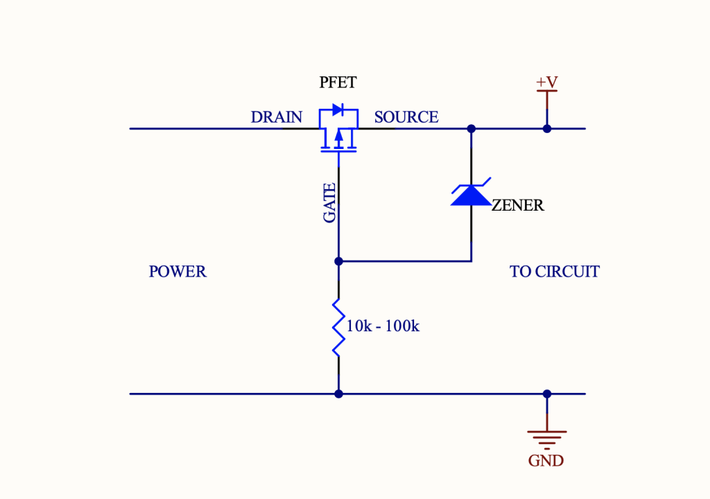
When we apply the correct polarity, the PFET operates by virtue of the body diode passing input voltage and biasing the gate such that the device turns on – and when it is on, the resistance of the device is so low, the diode is no longer in play. When reverse voltage is applied, this biasing cannot happen, so the device is off.
I have shown the circuit with an additional zener and resistor, but these may not be required as we will see as we select a device…
To select a device for our circuit, we need to consider the following parameters – maybe in this order –
VDS – drain to source voltage. This must be higher (I’d say much higher) than the battery or PSU voltage. If we are using 9V battery, I’d look for say 30V VDS, but some pedals can also use an 18V PSU – so consider the worst case.
Drain current and power. We need to make sure the device can sustain the worst case operating circuit current, and also (see next parameter) that the package can withstand that power level – in conjunction with RDS(ON). As above, I’d look for something way above what we expect / worst case – so that we are designing for longevity (good word!) and not stressing the power components.
RDS(ON) – drain source resistance. This is a huge one! Power loss is I2R, and Voltage drop is IR, so we need that R to be tiny – ideally tens of milli ohms – so we reap the benefit we are paying for…
VGS – gate to source voltage. If you can find a device that meets the above specs and has a VGS max greater than the input supply voltage, then we don’t need that zener and resistor (tie the gate to ground). The zener is literally there to clamp the VGS voltage to a safe level (see the datasheet). Eg if VGS is 8V, I might clamp it with a zener at 6 or 7V.
The resistor value is not critical – say 10k to 100k – protects the zener and limits current.
Quick note – RDS(ON) is a function of VGS, so check the datasheet for the typical applied VGS vs what max RDS(ON) you can expect! Ah, engineering circles of fun..
Some personal observations on selecting MOSFETs for this application: I found that very large (TO220 packages) had RDS(ON) in the right range – like the IRF5305 that I use on my development boards. I also found that there were quite a few nice PFETs in smaller surface mount packages that met the specs, but very few in something like a TO92 package or similar for my all through-hole builds. If you find something, post a comment or drop me a mail!
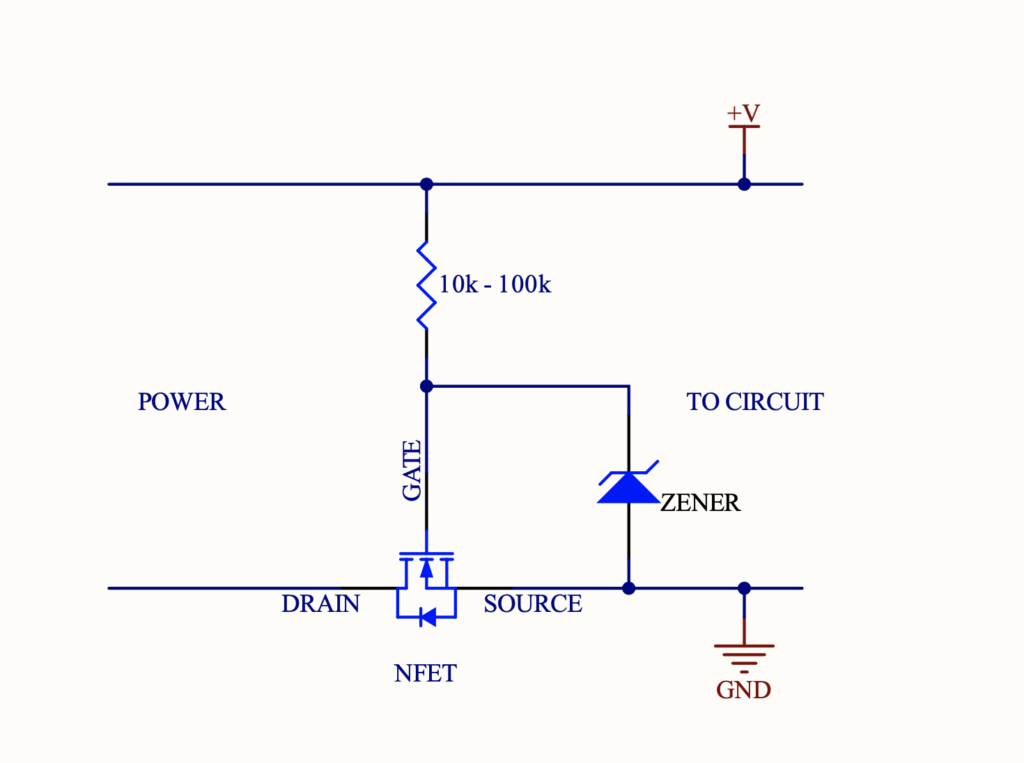
However, help may be at hand using an NFET as shown in the diagram below, and indeed NFETs can have very attractive features such as lower RDS(ON), might be lower cost and with more availability of devices.
Hope this is useful. Happy to answer questions, and take feedback.